Rigid Flex PCB Design Guide: Benefits, Challenges & Manufacturing
- Flex Plus Tech team

- Aug 12, 2024
- 5 min read
Updated: Sep 9, 2025

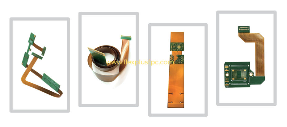
The picture above shows a rigid flex PCB. Due to the need for both flexibility and rigidity in today's complex electronic devices, as well as the increasing demand for smaller and more reliable electronic components, and their growing importance in various fields, rigid flex PCB boards have become increasingly widely used in different industries. In this article, let's take a look at what a rigid flex PCB is, its advantages and disadvantages, as well as the manufacturing process.
What is Rigid flex PCB?
In simple terms, a rigid flex PCB is a circuit board that combines rigid and flexible sections. The rigid sections are typically used for mounting components, while the flexible sections allow for bending and flexibility. This design allows for better adaptation to the assembly requirements of various devices. There are many different types for rigid flex PCBs; for example, both ends can be rigid with a flexible section in the middle, or one end can be rigid and the other flexible, and so on. As long as you can design it, Flex Plus can manufacture a product that meets your specific needs.

Major Design Challenge of Rigid flex PCB
The design and manufacturing process for this type of circuit board is more complex than that of a rigid PCB or flexible PCB. For example, it's necessary to avoid subjecting the flexible sections to excessive mechanical stress and prevent delamination in the rigid areas. Furthermore, ensuring a stable connection between the flexible and rigid sections is crucial.
To overcome these challenges, designers need to pay attention to the minimum bending radius of the flexible sections, component placement, and the overall layout of the circuit board.

Common Materials for Rigid flex PCB:
Rigid Section: The most commonly used material is FR4 (glass fiber epoxy resin).
Flexible Section: Polyimide film is the most prevalent material used.
Copper Foil: Since the flexible area needs to withstand repeated bending, RA copper is typically used; ED copper is more commonly used for the rigid section.
Adhesive or Non-adhesive Laminate: Used to bond the layers together, depending on the design requirements.
Coverlayer Film: Used to protect the copper circuitry in the flexible area.
Surface Finish: Used to protect the solder pads and ensure good solderability.
Material Selection Criteria:
Able to withstand bending, folding, or vibration without cracking.
Must not deform during soldering and reflow processes.
Low dielectric loss and stable impedance control.
Long-term durability under specific environmental conditions (temperature, humidity, chemicals, etc.).
The thickness should allow for flexibility while being strong enough to meet design requirements.
Cost is also an important factor to consider.
Manufacturing Process
Rigid-flex PCB combine the best of both worlds while enjoying unparalleled advantages, but their manufacture requires several key steps that require absolute precision and attention to detail.

Design and Layout: It all starts with designing the circuit board layout, considering each kind of requirement for both rigid and flexible sections.
Material Selection: It is very important to choose the material wisely as this will directly affect the performance and reliability of the Rigid-flexible PCB. It is choosing the right substrate for both the rigid and flexible layers.
Lamination: The compliant layers are laminated onto the rigid parts by a bonding process to assure good adhesion without hindering their flexibility.
Drilling and Plating: Drill holes to create via; Holes are plated with copper to create a conductive.
Photo Etching: The copper is photo-etched to create the desired traces on both the rigid and flexible portions of your design.
Assembly & Testing: In this stage, components are assembled on the PCB formed by earlier stages and then tested for reliability.
Is Rigid-flex PCB reliable?
The answer is yes; the reliability of flex-rigid PCB is unmatched. Because they can withstand mechanical stress, vibration, and harsh environments, they are ideal for industries such as aerospace, medical devices, and military electronics. In other words, in complex applications that cannot be achieved with rigid PCBs, rigid-flex PCBs provide a perfect solution.
It is widely used in compact, lightweight, functional design devices for applications with higher reliability requirements. For example, foldable screen mobile phones, smart monitoring bracelets, etc. In this case, it is crucial that the circuit board can bend without damaging itself. In addition, the use of Rigid-flex circuits also eliminates and reduces the installation of multiple connectors and cables, thereby improving the reliability of the overall service life.
Rigid-Flex PCB Pros and Cons
Pros
Design Flexibility: It enables engineers to tackle more complex circuit designs, allowing them to fully utilize their expertise to create circuits that fit diverse spaces and irregular shapes.
Compact Design: Rigid flex PCB effectively reduce board size by leveraging their advantages (rigid areas for component mounting, better space utilization), making them suitable for compact devices.
Enhanced Durability: Compared to rigid PCB, the flexible layer absorbs mechanical stress, preventing further damage.
Fewer Connections: Rigid flex PCB reduce the number of connections between boards, eliminating the need for connectors and avoiding circuit instability issues caused by multiple connections.
Cons
Increased Manufacturing Costs: The complexity of rigid flexible PCBs can result in higher production costs compared to rigid PCBs or flexible PCBs. These include unique materials and production processes.
Complexity: The added complexity of the design complicates the design process by determining the mechanical and electrical characteristics of both the rigid and flexible parts.
Longer Lead Times: The manufacturing of rigid flex printed circuits is a complex process, so the lead times are longer than for Rigid circuit boards.
Rigid PCB Vs Rigid-Flex PCB
Whereas traditional rigid circuit boards are inflexible, Rigid flex PCB boards combine the benefits of both flexibility and fortitude. This is good for applications that have a small form factor with an immense level of reliability. It means they eliminate more connectors and interconnects, reducing the number of failure points to give a tougher performance.
Working with an expert in rigid flex PCB manufacturing is the only way to maximize everything these hybrid circuits have to offer your product designs.
Some Cases of Flex Plus
FQA
Q1: What is a rigid-flex PCB?
A: Rigid-flex PCBs combine rigid and flexible layers, providing strength for component mounting and flexibility to connect complex circuits.
Q2: What are the advantages of rigid-flex PCBs?
A: They allow compact designs, absorb mechanical stress, reduce connectors, and increase reliability in demanding applications.
Q3: What are common design challenges?
A: Designers must manage bend radius, component placement, thermal management, impedance, and signal integrity issues.
Q4: Where are rigid-flex PCBs commonly used?
A: Industries like aerospace, medical devices, military electronics, foldable smartphones, and wearable devices.
Q5: Are rigid-flex PCBs more expensive than regular PCBs?
A: Yes, due to complex materials and manufacturing, rigid-flex PCBs typically cost more and have longer lead times.
Conclusion
The flexibility and reliability of Rigid-flex circuits make them an essential element in today's electronic layouts. Therefore, whether you are designing a small, lightweight consumer product or a critical aerospace workhorse, you should not overlook the capabilities and challenges of Rigid-flex PCBs. Partner with a proven rigid-flex PCB manufacturer, and your product will have the best performance, reliability, and durability.


Comments