Class 2 and Class 3 Flexible PCB for Automotive Applications
- Flex Plus Tech team

- Feb 9
- 4 min read
In automotive electronics, flexible PCBs are commonly used in sensors, cameras, lighting modules, control units, and interconnect systems, where vibration, thermal cycling, and extended service life are unavoidable. In this context, IPC class selection is not simply a specification detail, but a fundamental reliability decision during the flexible PCB design and manufacturing process.
Next, let's take a look at the actual differences between IPC Level 2 and Level 3 flexible printed circuit boards.
Understanding IPC Classes for Flex PCB
IPC-6013 defines three performance classes for flexible printed circuits. In automotive applications, Class 2 and Class 3 are the most commonly considered.
Class 2: Dedicated service electronic products with extended life requirements
Class 3: High-reliability electronic products where continuous performance is critical
While both classes can be used in vehicles, their design margins, inspection criteria, and reliability expectations are significantly different.
Key Differences Between Class 2 and Class 3 Flexible PCB
1. Reliability Expectations
Class 2 flexible PCB is designed for stable operation under normal automotive conditions, where occasional degradation does not result in system failure.
Class 3 flexible PCB targets mission-critical automotive electronics, where failure is unacceptable throughout the product’s lifetime.
In safety-related systems such as ADAS sensors or braking control modules, Class 3 is often required.
2. Conductor Width, Spacing, and Annular Ring
Class 3 imposes tighter control over conductor geometry:
Larger minimum annular ring requirements
Stricter limits on conductor width reduction after etching
Higher tolerance for registration accuracy
These requirements directly improve resistance to vibration-induced cracking and thermal fatigue, which are common in automotive environments.
3. Via and Interconnection Integrity
Via reliability is a critical factor in automotive flexible PCBs, particularly in multilayer and rigid-flex constructions exposed to vibration and thermal cycling.
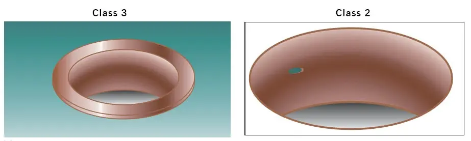
For IPC Class 3 flexible PCBs, via quality requirements are extremely stringent. Voids within plated holes are not permitted, as any discontinuity in the copper plating may compromise electrical continuity and long-term mechanical reliability under automotive operating conditions.
In IPC Class 2 flexible PCBs, limited voiding may be acceptable under controlled conditions. The acceptance criteria typically include:
No more than one void per plated hole
The total number of holes containing voids shall not exceed 5%
The length of any void shall be limited to no more than 5% of the total hole length
Any void shall occupy less than 90 degrees of the hole circumference
While these allowances may be acceptable for non-safety-critical automotive electronics, applications subjected to continuous vibration, temperature cycling, or long service life requirements generally benefit from Class 3 via integrity standards to reduce the risk of fatigue-related failures.
4. Coverlay and Adhesion Requirements
Coverlay adhesion is critical in flexible PCB reliability:
Class 3 requires higher peel strength and stricter limits on delamination
Edge lifting, blistering, or adhesive separation that may be acceptable in Class 2 can be rejected under Class 3 criteria
This becomes especially important near connectors, stiffener edges, and dynamic bending areas in automotive assemblies.
5. Inspection and Acceptance Criteria
Acceptable Conditions for IPC Class 2 and Class 3 Flexible PCB
For both IPC Class 2 and Class 3 flexible PCBs, certain minor defects may be considered acceptable provided that they do not affect electrical performance, mechanical integrity, or long-term reliability. The following acceptance conditions typically apply:
The total area affected by defects shall not exceed 1% of the surface area per side of the printed circuit.
Defects shall not reduce the spacing between conductive features below the specified minimum conductor spacing.
The span of any blistering or delamination shall not exceed 25% of the distance between adjacent conductive features.
Blistering or delamination shall not increase in size as a result of multiple thermal exposures or manufacturing-related heat tests.
Defects shall not reduce the minimum specified distance between the board edge and conductive features. If no minimum distance is specified, any micro-crack shall not exceed 2.5 mm in length.
Class 3 flexible circuit boards require more rigorous visual inspection, stricter defect acceptance criteria, and a higher sensitivity to rejecting both cosmetic and functional defects. From a manufacturing perspective, this means tighter process tolerances and higher production costs, but it also leads to improved product reliability in practical use.
Which IPC Class Is Suitable for Automotive Applications?
Typical Automotive Use Cases for Class 2
Class 2 flexible PCB is commonly used in:
Interior lighting systems
Infotainment modules
Display interconnections
Non-safety-related control panels
These systems require durability but are not considered life-critical.
Typical Automotive Use Cases for Class 3
Class 3 flexible PCB is recommended for:
ADAS sensors and cameras
Powertrain monitoring systems
Battery management systems
Safety-related control electronics
In these applications, long-term electrical and mechanical stability is mandatory.
Cost vs Reliability Trade-Off
Choosing Class 3 flexible PCB increases:
Manufacturing complexity
Inspection time
Overall cost
However, for automotive electronics exposed to vibration, heat, and extended service life, the cost of failure often exceeds the cost difference between Class 2 and Class 3.
Early alignment between design, manufacturing, and automotive quality requirements helps avoid costly redesigns later in the project lifecycle.

Final Considerations for Automotive Flexible PCB Design
Selecting between Class 2 and Class 3 flexible PCB should be based on:
Functional criticality of the automotive system
Environmental stress conditions
Expected service life
OEM and professional supplier requirements
Working with an experienced flexible PCB manufacturer ensures that IPC class selection, material choice, and process control are aligned with automotive reliability expectations.


Comments